
The growth of wireless electronics continues in several important ways. While this is good to the extent that new applications contribute to improving our quality of life, the competition for bandwidth on the electromagnetic spectrum becomes more challenging with every passing minute.
Consider the many ways that wireless technologies are expanding into new applications. Applications that were non-existent or unusual a decade ago are now common and essential parts of daily life.
The internet of things (IoT) continues to grow into agricultural, smart home, building management, environmental monitoring, smart utilities, security, smart city, and other applications, while consumer demand drives increasing use of wireless electronics for personal communications, computing, entertainment, fitness tracking, and more. Even something as simple as a mobile phone might contain transmitters for 4G, 5G, GPS, NFC, Wi-Fi, and Bluetooth.
The automotive industry is also using increasing amounts of electromagnetic spectrum, as the drive toward vehicle-to-everything (V2X) technology connects vehicles to other vehicles, infrastructure, pedestrians, infotainment systems, satellites, and passenger devices.
Wireless communications are also helping to revolutionise healthcare, as remote patient care, embedded and wearable devices, wireless operating rooms, surgical robots, hospital robots, and mobile imaging become more common.
These wireless communications technologies make wireless coexistence more important and more challenging than ever, and many manufacturers rely on standards to guide their coexistence testing. In the US, for example, there is the American National Standards Institute (ANSI) known as ANSI C63.27 to guide testing. The C63.27 document, entitled American National Standard for Evaluation of Wireless Coexistence, outlines four coexistence test methods, and each has its advantages and disadvantages.
Method 1: RF conducted test uses RF cables to combine and transmit signals between your equipment under test (EUT), its companion device, and some combination of transmitters or signal generators that simulate unintended signals. Because this method uses cables to conduct the signals, it is very repeatable. The use of cables, however, makes it less realistic than some other methods.
Method 2: Multiple chamber test uses two shielded anechoic chambers, one for the EUT and the other for its companion device. RF cables connect the two chambers, and an attenuator in the path between the chambers allows you to vary the signal strength. You also use transmitters or signal generators or both to pump simulated unintended signals into one or both chambers. Because this is a radiated test, it does not require cables to the EUT or the companion device. However, it does require that you have multiple chambers, and this adds significant cost.
Method 3: Radiated anechoic chamber test is conducted in a large, shielded room that contains the EUT, the companion device, and the interfering signal generators or transmitters. This extremely flexible method allows for a wide range of distances and orientations between the various items. You can also move equipment and rotate antennas in real time to see how the EUT’s key performance indicators (KPIs) change under various circumstances. The major drawback to this approach is that the cost of building and maintaining a shielded room of this type may easily be several millions of dollars. There are test houses that rent space and equipment for this purpose, but arranging for time in the room often must be done well ahead of time, and if your EUT fails, there may be a long wait for a subsequent test.
Method 4: Radiated open environment test is like radiated anechoic chamber test, but it is performed in an open environment, which means there may be unintended interference from other users. Like radiated anechoic chamber test, it is extremely flexible, but it is much less expensive because it does not require an anechoic chamber. Of course, the electromagnetic context of the open environment is less predictable than that within an anechoic chamber, so the test is not as repeatable. On the other hand, the unpredictability of the environment adds an element of “real life” to the method.
Your device passed, but is that good?
Regardless of which test method you choose, passing a test may or may not indicate that your device is ready for the real world.
The ANSI C63.27 document, for example, gives excellent descriptions of the four test methods, but it necessarily leaves many factors of the test design to the judgment and discretion of the device manufacturer.
There is in fact wide latitude in how the four methods are used, so passing a coexistence test may mean that your device performs robustly, or it may mean that your coexistence test is insufficiently challenging.
Before designing a coexistence test plan, test engineers should work with the cross-functional product development team and make sure that they understand answers to the following questions.
- What is the purpose of the EUT, and what is the intended electromagnetic environment where will it be used? Consider challenging corner cases, such as a damaged building with several disabled access points or a busy emergency room with several active police and emergency responder radios.
- What testing tier is appropriate for your EUT? Is it cost effective but only uses a minimal set of unintended test signals? Or is it more appropriate to use unintended test signals that provides greater confidence? Or does your device demand a type of testing, which is appropriate for mission-critical and life-sustaining devices?
- What is the functional wireless performance (FWP) of the EUT, and what RF bands and communications protocols does it use? Does it transmit and receive on multiple protocols simultaneously?
- What are the KPIs, how will you monitor them, and what thresholds are considered passing? Engineers with expertise in wireless communications consider metrics such as bit error rate, packet error rate, throughput, latency, jitter, sensitivity, lost packets, number of retransmissions, and so on.
- What are the KPIs from the end-user perspective? Does a delayed, missed, or slow transmission causes a timeout or error in the user interface?
- For medical devices, what is the impact of wireless performance on patient safety and device efficacy? Will time-sensitive treatments and diagnoses be noticeably delayed by poor wireless coexistence? Will wireless performance limitations lead to errors that a person with limited medical or technical knowledge will not be able to recognise and overcome? Remember that many medical devices are used by patients directly, and these patients may have limited technical understanding or impaired cognitive skills.
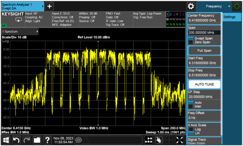
- What sorts of unintended signals will you use as interferers? How will you produce and monitor the unintended signals? What wireless standards will you include in your interference set? Will you use relatively simple signals and protocols, or will you use more challenging modulation methods such as IEEE 802.11ax with advanced quadrature amplitude modulation (1024-QAM) (shown below)?
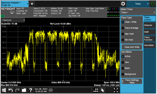
- Will you use one interfering signal at a time, or will you combine multiple signals for greater challenge? For example, the image below shows three IEEE 802.11ax signals with 1024-QAM, but varying power levels, idle periods, and total frames.
What non-standard interferers will you include in your test plan? For example, microwave ovens radiate electromagnetic energy around 2.4-GHz, which is a popular ISM band used by baby monitors, Bluetooth devices, Wi-Fi, cordless telephones, and many other common devices.
By carefully considering these questions, you will increase the likelihood that passing your coexistence test means your device is ready for the real world, and not simply the beneficiary of an insufficiently rigorous test.
Author details: Brad Jolly, Senior Applications Engineer, Keysight Technologies


