
However, not all space applications require the same level of radiation protection. While deep space applications, for example, use costly radiation-hardened components today’s new space applications, where LEO (low earth orbit) and MEO (medium earth orbit) satellites roam, only require “radiation-tolerant” components and circuitry.
Wave and particle radiation
As referenced in Figure 1, wave radiation and particle exposure are related, but the system effects are different. Individual particles have little mass but can be accelerated to very high velocities. They can also carry charges - generally positive when negative-charge electrons are stripped from atomic orbits.
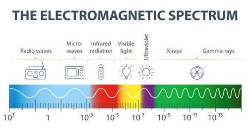
Figure 1: The radiation spectrum
Particle radiation can cause physical damage, particularly to semiconductor crystal lattices and that damage can prove to be either permanent and/or cumulative. Systems also experience temporary upsets when electrons are dragged into depletion regions and make a non-conducting region conduct.
Alternatively, if positive ions replace doping atoms in a crystal matrix, permanent damage can result, making a semiconductor conduct when it shouldn’t causing permanent damage as a result of circuit malfunction.
Much of the radiation damage is cumulative, so mission length will always be an inescapable factor.
Best practices
In today’s fast-paced new space business environment, costs to launch and to replace dead satellites are substantial, so careful design is important.
Select components for radiation tolerance. Some semiconductor process nodes have improved radiation performance. Bipolar semiconductors can be selected for displacement damage ratings, while wide-bandgap (GaN) FETs have inherent radiation tolerance. Some epoxies and aluminium electrolytic capacitors outgas in a vacuum, making them inappropriate for use in space environments.
Product lots should be sample-tested for radiation performance to account for lot-to-lot variations.
Multiple instances of systems can be implemented. Physical redundancy is a safeguard. If one fails, another can take over. In some systems, there are three systems operating in parallel so that if one disagrees with the other two, its output can then be ignored.
Power MOSFETs can be de-rated so that after inevitable VGS threshold degradation, the device is still functional at the end of the mission life.
Shielding can protect sensitive electronics, but if the particle energy is high enough, cascading shield particles can add to the problem.
Circuitry can be added to monitor performance, disconnect and restart inconsistent systems if a fault is recoverable.
But, regardless of design strategies and power supply topologies, new space electronic systems must be rigorously analysed, simulated and tested for environmental and radiation performance.
Delivering a competitive advantage
Soft-switching topologies (versus hard-switched power converters) can make a system less sensitive to parasitic effects like ringing that increases voltage stress on switching components.
Factors for evaluating a topology include power density, efficiency, transient response, output ripple, electromagnetic interference (EMI) emissions and cost.
Switching loss occurs during turn-on and turn-off of a powertrain’s MOSFETs via gate-charge requirements and drain-to-source capacitance. Switching losses increase with, and thus limit, switching frequency. Body-diode conduction losses detract further from power-conversion efficiency in hard-switched converters. Though GaN FETs do not have a physical body diode, they do have a reverse conduction mode clamping at several volts and this can make the GaN dead-time conduction period very challenging to manage.
In a synchronous, hard-switched buck topology, the high-side FET turns on when it has the maximum voltage across it and conducts its maximum current during the turn-on portion of the operating cycle (see Figure 2, left side). The greater the input voltage, the higher the power loss, so converters in high voltage-ratio applications (e.g., 28V to 3.3V) deliver poorer efficiency than the converters with greater conversion ratios (e.g., 5V to 2.5V).
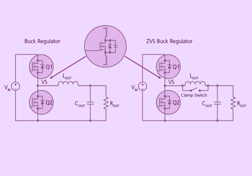
Figure 2: Topology parasitics. Conventional, hard-switched buck converter (left) versus zero-voltage switched (ZVS) buck converter (right)
The benefits of soft switching
Soft switching reduces switching losses. One example of soft switching is the zero-voltage switching (ZVS) technique, which improves conversion efficiency across a range of power topologies. ZVS switches the high-side FET on when the voltage across the switch is at or near zero (see Figure 2, right side).
Operation of a clamp switch with the ZVS technique allows the converter to store a small amount of energy in the output inductor when both high-side and low-side switches are off. The converter uses this otherwise-wasted energy to discharge the high-side FET’s output capacitance and charge the synchronous FET’s output parasitic.
Taking the FET’s output capacitance out of the switch’s turn-on behaviour will help to desensitise FET selection regarding Cgd and, consequently will allow designers to focus on on-state channel resistance instead of traditional figures of merit such as the product of channel resistance and gate capacitance.
This method of driving the high-side FET during turn-on avoids exciting the switch’s parasitic inductance and capacitance, which tend to resonate, inducing large voltage spikes and ringing in hard-switched topologies (see Figure 3a). By eliminating spikes and reducing ringing (see Figure 3b), ZVS removes a power-loss term and eliminates a source of EMI emission.


Figure 3a & b: Hard-switching versus soft-switching waveforms
Eliminating the voltage spikes from the switching behaviour also allows designers to select lower-voltage FETs with lower RDSON to improve efficiency.
Vicor is among a number of companies to have developed and employ soft-switching techniques in its radiation-tolerant power module solutions for powering high-performance communication ASICs (see Figure 4) dedicated to MEO and LEO satellite applications. The system modules use ZVS buck-boost topology for the PRM and ZVS and ZCS Sine Amplitude Converters (SAC) for both the BCM and the VTM.
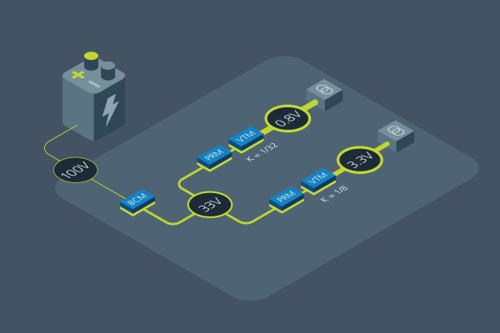
Figure 4: High-power resonant (ZVS and ZCS) topology modules.
The small size of the VTM allows placement as close as possible to the ASIC. Optimising the power distribution network (PDN) is critical when dealing with high currents consumed by modern ASICs, FPGAs, CPUs and GPUs.
Consequently, Vicor’s modules combine soft-switching solutions, rad-tolerant active components and automotive-qualified passive components.
To mitigate the single event function interrupt, all radiation-tolerant modules include completely redundant powertrains operating in parallel. If one powertrain gets upset due to a single event, its protection circuits force a power-off-reset. During the reset interval, the redundant powertrain carries the full load and after the reset both powertrains operate in parallel again.
Among many other factors, selecting a topology and switching mode are important factors when it comes to designing new space power converters.
Author details: Ken Coffman, Senior Field Applications Engineer & Salah Ben Doua, Principal Applications Engineer


