In this context, ‘standardised’ means separating individual functions from their eventual implementation as a hardware, sensor, driver, actuator or software component. Instead of distributing the models across various levels, the individual domain-specific descriptions can be combined within a single functional abstraction, thereby eliminating the lengthy mapping process.
Communication between individual functions is via signals standardised as either software/internal to device, bus, or electrical/wireless. A set of rules from a detailed options/variants model links all artefacts. The component models for hardware, software, network and electrical can thereby be integrated and their semantic dependencies validated in real time using design rule checks.
In this way, it is possible to capture the technical, variant-driven content of the downstream implementation domains – hardware, software, network and electrical – as early as the functional abstraction level in order to validate this content across all variants and to flow data on to the detailed implementation domains.
To illustrate this approach, figure 1 shows a number of functional blocks – such as software functions, driver components, sensors and actuators –displayed within a single abstraction level. The signals between functions are shown according to their required implementation in software, electrical signals on a PCB, electrical signals in a wiring harness and signals on a network.
The individual type allocations correspond to implementation requirements for the downstream platform. If a function is of the software type, this means that the function is treated as a SW component in the downstream allocation to a platform: it should therefore be allocated to a control unit and not to a purely electrical component. Note also that some of the functions and signals are optional, corresponding with the options/variants model. Indeed, substantial information can be added within this abstraction, if it is known, such as signal bit size or timing requirements.
Functions can be organised hierarchically and function signals can not only reference their originating functions (if from an external functional design), but also be made available across platforms and projects via a signal library.
Logical platform
By capturing the functional design data as described, the downstream implementation domain data – hardware and software, bus systems and electrical distribution – can be created automatically after deploying the function and their signals on a platform design, with option/variant relationships always respected.
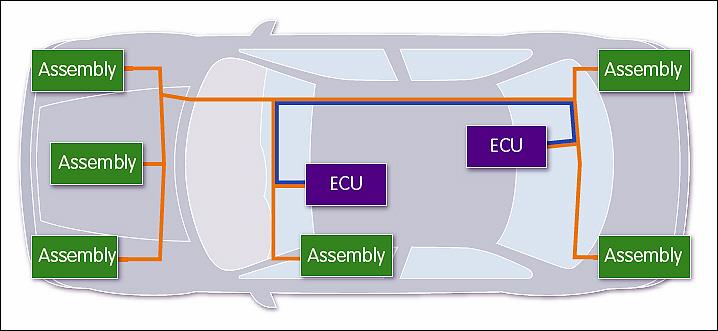
To do so we first define a logical platform. While this can be created from a 3D model in the form of a physical topology (see figure 2), it can also start as an abstract (non-physical) logical network topology. By blending individual functional components with an options/variants model, a logical platform can encompass an individual car, a range of cars or all possible derivatives of a car platform, including variations in hardware, software, network, electrical and even mechanical detail.

A schematic platform architecture with function containers and connecting pathways
The individual nodes of the platform are standardised as resources: electronic control units (ECUs) or line replaceable units (LRUs), electric assemblies, and electricity or earth conductors. They can be coupled electrically or via bus systems – such as CAN, LIN, Flexray, Ethernet and ARINC 429 – or indeed by optical or radio connections. These communication pathways are called carriers.
Note that this principle can not only be applied to automobiles, but also to trucks, buses, off-road vehicles, aircraft and other complex electromechanical machines such as industrial printers and medical equipment. Furthermore, carriers providing the means of connecting functions do not have to be physical – they could be wireless. Meanwhile, extended ‘system of systems’ constructions, such as V2X or a multi element air defence system can be modelled in this way.
Allocate, validate and synthesise
Next, we allocate functions into the logical platform, either manually or automatically using rules. While doing so, the functions are interrogated as to their type. For example, a software component is created from a function of the type software and then allocated to a control unit. The signals passing between functions are assigned to carriers as software, electrical, power or network signals within the logical platform.
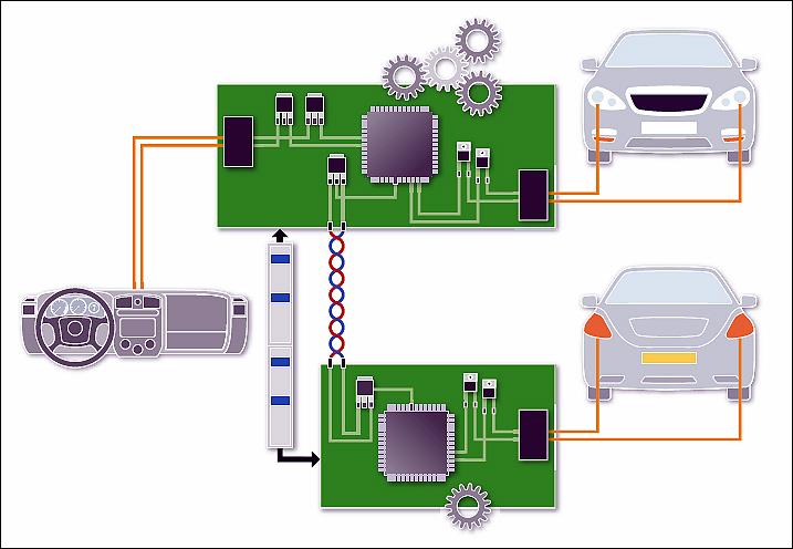
The resulting detail is the integrated implementation across the four domain types (hardware, software, multiplexed network communication and electrical) of the functional description. This is visualised in figure 3 for a simple lighting system. Semantic consistency can be analysed in real time using design rule checks and any necessary warnings or error messages generated. Technical metrics are calculated instantly, allowing to iteratively optimise the function and signal deployment towards a set of Key Performance Indicators.

A representation of multi domain implementation synthesis
Beyond automotive
The methodology and process flow described here mostly uses illustrations from automotive use cases, but is nevertheless just as suitable for application by the avionics, military and complex machinery industries.
The Function Design paradigm allows to describe functionality which is to be implemented in systems and their respective components as implementation independent: The function design approach is just as applicable for implementation in a machine as it is in a car.
The industry specific technical implementation is defined on the platform design level. From there, the actual domain specific content is synthesised during the distribution of the functions and their signals into the respective platform containers, such as ECUs and LRUs, or electrical, optical and wireless multiplexed network carriers.
Summary
Existing approaches based on UML or SysML-like meta-models are less suitable, because of the technical effort and knowledge needed. The related complexity allows virtually no scope for achieving the adequate or necessary level of detail for a comprehensive evaluation in the available time. By contrast, the approach described in this article uses a functional abstraction in which the implementation-related data and artefacts are combined into standardised functional models, instead of distributing them across different, in some cases redundant levels. The result is digital continuity throughout the design process.
Author profile
Hans-Juergen Mantsch is manager of strategic programmes for Mentor Automotive.


