
The development of wireless automated communications between vehicles and infrastructure – known generically as V2X – is driving continuous improvement in road safety. For example, all vehicles approaching a crossing can exchange information about speed and direction. This makes it possible to detect potential collisions, issue appropriate warnings and initiate countermeasures autonomously.
But, in order to work effectively, information between vehicles needs to be accurate, even under poor transmit conditions. Strong coding and specialised protocols cannot compensate for the loss of signal, so if a receiver cannot handle fading or time variations, it will not be able to detect and process the signal received at the antenna.
The RF transmitters and receivers in on board (OBU) and road side units (RSU) need to exhibit certain characteristics and RF tests are required to verify them. The two lowest layers of the OSI model factor into these tests because they are responsible for the physical transmission of the data message:
* The physical layer is responsible for the movement of data via a transmission medium. In the case of V2X, data is wirelessly transmitted via the air interface using specific modulation modes, carrier frequencies and bit rates.
* The data link layer has two components: the MAC and LLC. The medium access control (MAC) layer regulates access to the transmission medium for multiple subscribers and is relevant for RF measurements. The logical link control (LLC) layer handles tasks such as error detection and correction at the protocol level.
Protocol level tests are not suitable for verifying RF characteristics; they check the bit stream – generated in the LLC layer from the received signal – is processed correctly and the RF signal at the receive antenna is ignored.
All protocol level tests have one prerequisite: that the signal with the data message has been received at the vehicle antenna and converted into a bit stream. This bit stream can contain bit errors, but only as many as can be corrected using channel coding. For error free processing, the data message must appear in the application layer precisely as it was received at the OBU antenna. This triggers actions such as a warning message or automatic braking.
The OBU’s RF module – the MAC layer and the physical layer – must therefore meet certain minimum requirements, including power and frequency accuracy and packet error rate. In addition, the transmitted signal must not interfere with any transmission technologies in adjacent frequencies. These characteristics can only be verified with RF tests, not protocol tests, because any interference in the transmitted signal is conducted to the receiver via the OBU’s RF module.
So how can RF module requirements be tested, ensuring that transmitted data is received? In the mobile sector, smartphones are subjected to regulatory and conformity tests, with some providers performing additional tests.
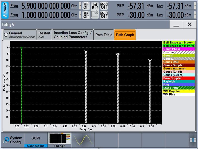
A signal generator plot showing a fading profile for V2X at 5.9GHz
The automotive industry tests components and electronic control units in the lab, on testing grounds and on public roads. In the field, weather can affect the RF characteristics of the radio link and the test setup and test sequence will depend on the vehicle used and antenna location.
Changes to field tests are not always practical for a device in the development stage, so what is required is realistic testing and conducted tests provide an alternative. A test system simulates the transmission channel, while a cable replaces the radio link. These types of RF tests can be performed for each prototype and each time the software or hardware is changed. Advantages include:
* The tests can be performed at any time and at low cost.
* The test conditions are clearly defined at all times and can be changed at any time, irrespective of outside influences.
* Clearly defined test sequences, when performed under the same conditions, lead to comparable results.
* Reproducible and comparable results facilitate debugging.
* Parameters can be easily modified.
* Multiple tests can be combined into test sequences and then performed automatically.
* Certain RF tests, such as error vector magnitude or RX sensitivity tests only make sense as conducted tests.
Depending on the selected scenario, channel simulation simulates the physical attributes of the transmission path exactly. Modern signal generators can also simulate the special V2X fading profiles in real time.
While field tests still make sense, channel simulation can simplify testing, supporting development in the lab easily and cost effectively.
Detecting RF problems
In order to compare the test results of the various hardware and software versions of a V2X unit, all test procedures must be clearly defined. Some countries have defined four categories of test specifications for V2X systems:
* TX in band. The test cases in this group test the transmitter (TX) characteristics, for example maximum and minimum transmit power, frequency accuracy and modulation accuracy.
* TX out of band. Unwanted transmit power outside of the allowed frequency band must not disrupt other technologies. TX out-of-band test cases measure transmit power and compare it against the allowed limit.
* RX in band. This category tests the receiver (RX), for example by measuring the lowest receive power at which the received signal can still be decoded or by measuring performance with fading.
* RX out-of-band. Specialised test cases measure whether the OBU or RSU emit transmit power unintentionally in other frequency bands when the transmitter is switched off.
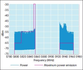
A TX out of band test. The transmit power (blue line) of an IEEE802.11p unit exceeds the allowable limit (red line) at multiple points. Frequencies from 5855MHz are reserved for V2X in Europe and the US.
Various plug tests for V2X have shown that TX out of band and fading tests are problematic for many devices under test, but it is possible to detect these problems during development using the appropriate instruments. RX tests can be performed with a signal generator capable of generating a V2X signal, while a signal analyser covers the TX test cases. Depending on the analyser’s dynamic range, a filter for the V2X signal is needed to cover the broad frequency range of the out of band measurement.
Currently, various wireless technologies are under discussion for implementing V2X communications, in particular WLAN IEEE802.11p, LTE and 5G and a variety of test solutions is available. For IEEE802.11p, the TS-ITS100 RF test system from Rohde & Schwarz contains the complete package of global test cases.
For out of band tests, it permits measurements up to 18GHz and can accept filters as needed for various regions. The system hardware is already set up to handle diversity and multiple input multiple output antennas. IEEE802.11p tests pose a special challenge in that no defined uniform interface to IEEE802.11p units exists. In order to configure the unit for a test case, the test software must address each unit with individual commands. The test system already contains plug ins for many units to allow fully automated testing.
Safety-critical messages must be transmitted reliably and quickly in every environment and traffic situation. Protocol tests alone are not sufficient because they do not test the circumstances under which the transmit signal arrives at the receiver. Only RF tests can ensure that the minimum physical requirements are met by OBUs and RSUs, so that lives can be saved during emergencies.
Author profile:
Dr Thomas Brüggen is project manager, RF Test Systems for Intelligent Transport Systems, with Rohde & Schwarz


