
Silicon vendors are coming up with new control processors with features and hardware support to implement algorithms efficiently, and in response the power conversion industry is turning to model driven development as a solution. However, the model’s performance needs to get closer to the final product performance so as to reduce the risk of hardware changes and delays.
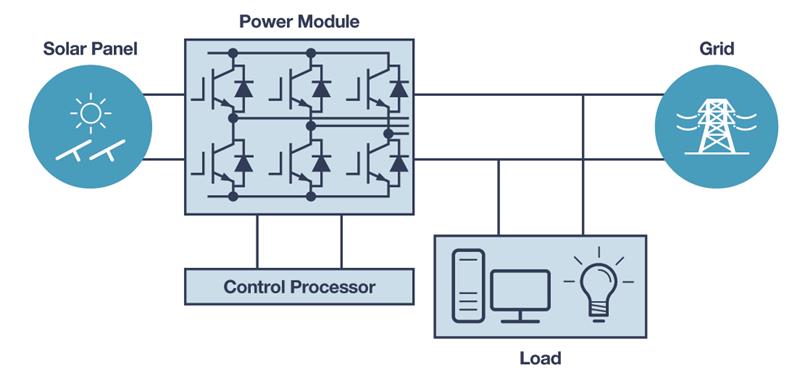
Consider a simplified diagram of a grid-tied residential solar inverter (Figure 1). The solar radiation on the solar panel generates dc proportional to the intensity of the radiation. The converter converts this dc to ac. Current and voltages from various points in the signal chain are sensed by appropriate sensors and will be fed to the control processor in the inverter. The algorithm running on the control processor analyses these signals and controls the power modules such that the generated current and voltage are of required frequency, magnitude, and phase with the grid. In this case, the solar panel acts as the power source, and the grid and appliances act as the sink. In a different power conversion system, the sources and sink would be different, but most of them will fall into the structure shown in Figure 2.
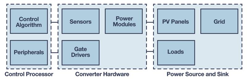
The primary aim of a power conversion system/algorithm designer is to arrive at the right components and algorithms for the block’s control processor and converter hardware and meet the desired performance for all source and load variations. So, it is important to clearly know the environment the system is going to operate in while designing the system.
In a model driven development, the designer first creates the model of the converter, simulates the expected variation, and verifies that the model works as expected. Most often the modelling tools will provide models and library blocks for modelling sources and sinks. For example, Simscape Power Systems from Mathworks has models for grids, photovoltaic (PV) panels, and various loads that can be used to simulate and verify various use cases of the system.
Structuring the Model
It is important to structure the model in a modular way with the right interfaces. Modelling tools typically provide various options to group the components at appropriate levels of abstraction and for reuse. Simulink has provisions to create subsystems, library models, or reference models.
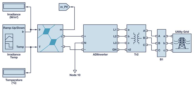
A top-level view of a Simulink model can be seen in Figure 3. Here, the power converter and control processor are encapsulated into a subsystem labelled as ADIInverter. Solar panel and grid models available with Simscape Power Systems are used to model the source with provisions to configure intensity and temperature.
The ADIInverter subsystem can be further partitioned hierarchically into control processor and control algorithm blocks.
All blocks other than the control algorithm running on the control processor are hardware blocks. So, the accuracy of simulation reflecting all the constraints of these components is the most important criteria.
The interfaces of these blocks are analogue signals and the most appropriate choice for these are continuous models. The block control algorithm is meant for running on a MCU and should only use discrete states and fixed steps. It’s better to keep that as a separate model with different configuration and solver settings and reference that model from the top-level model.
Solver Step Size and Data Types
The speed and accuracy of the simulation is mainly decided by the solver type and step size. A small step size will give more accurate results but will make the simulation run slower. A continuous solver with a variable step size should work in most cases.
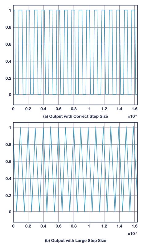
However, when the switching frequencies are high, manual adjustments for the maximum step size may be required, e.g. PWM generation at a switching frequency of 100 kHz (as shown in Figure 4a, see page 8) may become distorted (as shown in Figure 4b) if the step size is large. It is always a good idea to check the output of the fast switching devices to confirm that the step size is sufficient.
Since the control algorithm runs on a MCU , it should be using a discrete model with a fixed step size. The step size used should be the greatest common divisor (GCD) of the sampling period used in the system. Most often the modelling software chooses this automatically.
The data types used also decide the accuracy of simulation. Simulation with double precision arithmetic will always be more accurate than a simulation with single precision arithmetic. For simulating the hardware blocks, it is recommended to use the highest data type supported by the modelling software. But for the control algorithm, we want to get the performance of the algorithm the same as it runs on the control processor and not more accurate. So we should be using the data type supported by the control processor. Modelling software may support automatic conversion from a floating-point data type to a fixed point that will help to make the development faster.
Sampling Period and Precision
The current and voltage signals sensed by the sensors at various points in the power conversion signal chain are made available to the algorithm through analogue-to-digital converters (ADCs) of the control processors. The sampling rate for the ADC is mainly decided by the switching frequency of power modules and how fast it should be controlled. The sampling frequency has significant impact on the control algorithm performance and dynamics. So, simulation should be done by choosing the appropriate sampling rate for the system. The ADCs for control processors accept input only in predefined ranges. The output of the sensors should be normalised in a way that the range of the sensed signal fits exactly in the range of the ADC.
The resolution and accuracy of an ADC also varies from one processor to another and this plays a significant role in algorithm performance. High accuracy ADCs help to control the output better and help to simplify the algorithm and to reduce the control frequency for a specified control criteria. To get an accurate simulation, these characteristics should be reflected in the model.
Code Generation
All silicon vendors provide evaluation platforms for developing algorithms on their processors. It would give additional confidence on the performance of the algorithm if we can run and verify the algorithm performance on the evaluation hardware, but compilers for the embedded processors normally accept only C/C++ code and is typically time consuming to develop these codes manually during the modelling and verification stage. So, in the past, this stage has been pushed to the later stages of development.
Fortunately, most of the modelling software now supports the provision to generate codes automatically from the model. The model for the control algorithm can be configured to generate codes with predefined API. The simulation tools also provide a PIL option to run the generated code on the target directly from the modelling environment. In PIL simulation, the input and output of the control algorithm are exchanged with the evaluation board through interfaces such as UART.
Typically, the modelling and simulation software provide support for generating C code - targeting a broader range of processors. It is important to make use of such features to get the best performance out of the processor.
Modelling tools provides provision to replace part of the codes with custom codes or an entire algorithm block with a different code. For power conversion algorithms, optimised code can be generated by providing handwritten optimised routines for common algorithm blocks such as direct quadrature zero (DQZ) transforms, phase-locked loop (PLL), etc.
Apart from the control algorithm code, the control processor also needs codes for configuring the peripherals such as ADC, PWM, etc. and a framework code for maintaining the timings and other functionalities of the system. The modelling tools can be used to generate the code for these as well. However, the framework codes are expected to do much more than run the control algorithm.
HIL Simulation
The simulation of the power modules and the system normally runs on a host PC. Even in PIL simulation, only the control algorithm runs on the target control processor. All other parts of the system are simulated by the modelling software on the host machine. Since this simulation takes so many resources and as much execution time, it is not possible to run these in real time in the software. The system dynamics and performance of ADCs and PWMs are not verified in such testing. HIL simulation hardware overcomes this drawback by using field programmable gate arrays (FPGAs) to simulate the converter components, sources, and sinks. It helps to run the entire simulation in real time and to see the actual effect of ADC sampling and PWM control. The HIL hardware is typically provided by separate vendors with a provision to interface control processors. It should be noted that HIL platforms won’t be able to simulate the detailed switching characteristics of the power modules. These effects should be analysed separately to minimise the risk while taking it to the final product.
Conclusion
While modelling tools have greatly improved during recent years, it should be noted that there are some characteristics such as electromagnetic compatibility (EMC) that cannot be verified in a simulation environment.
It is important to identify these characteristics and analyse and verify through alternate methods.
The steps explained here, have been successfully employed in designing and developing control algorithm targeting ADSP-CM41x processors for an inverter with 3-level ANPC topology.
Author details:
Bijesh Poyil is an engineering manager at Analog Devices India, Bangalore and Martin Murnane is system architect for the Energy Storage and Conversion Team, at Analog Devices in Limerick, Ireland.


